

General Introduction:
This product is a transceiver module designed for 40km optical communication
applications. The design is compliant to 40GBASE-ER4 of the IEEE 802.3ba standard. The module converts 4 inputs channels (ch) of 10Gb/s electrical data to 4 CWDM optical signals, and multiplexes them into a single channel for 40Gb/s optical transmission. Reversely, on the receiver side, the module optically de-multiplexes a 40Gb/s input into 4
CWDM channels signals, and converts them to 4 channel output electrical data.
The central wavelengths of the 4 CWDM channels are 1271, 1291, 1311 and 1331 nm as
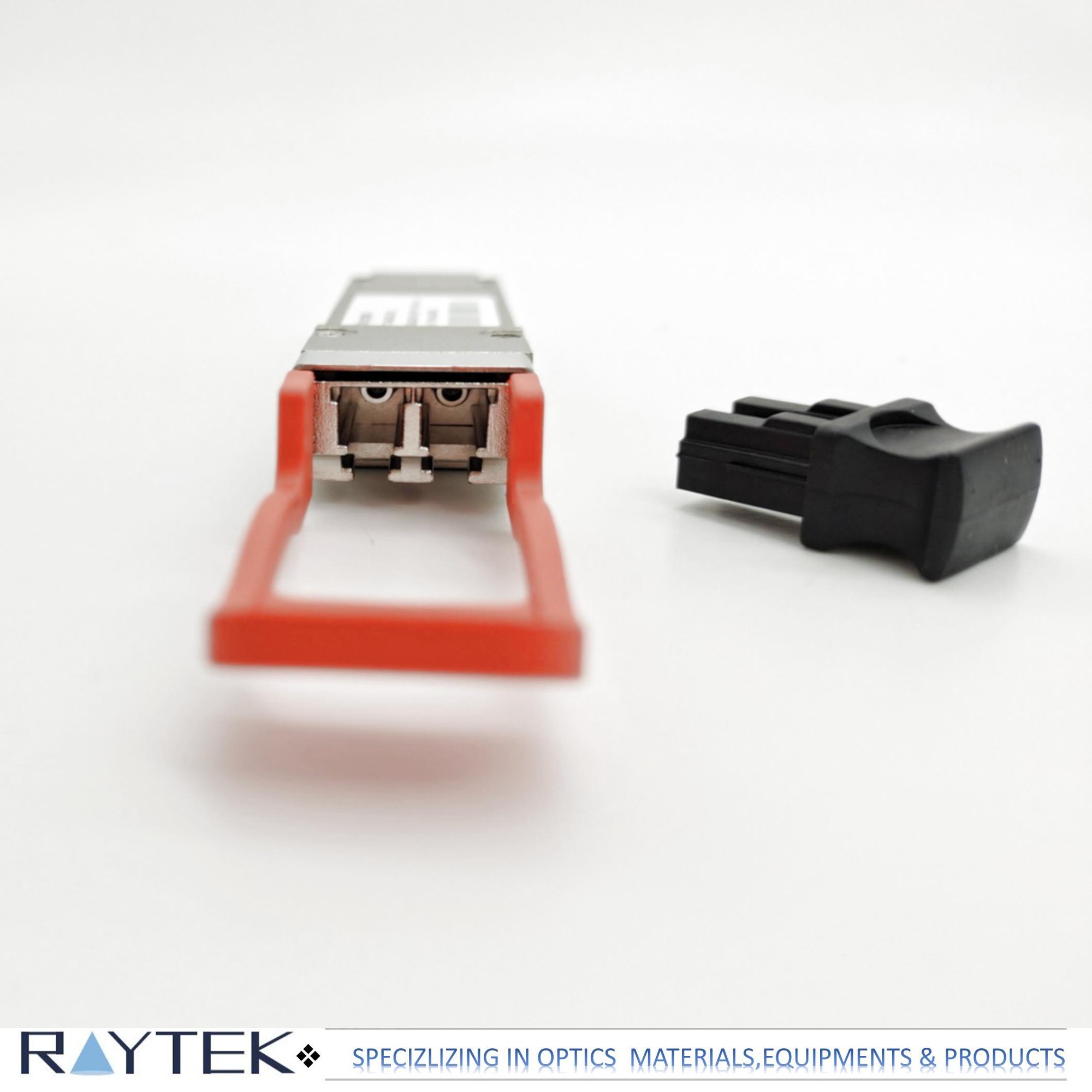
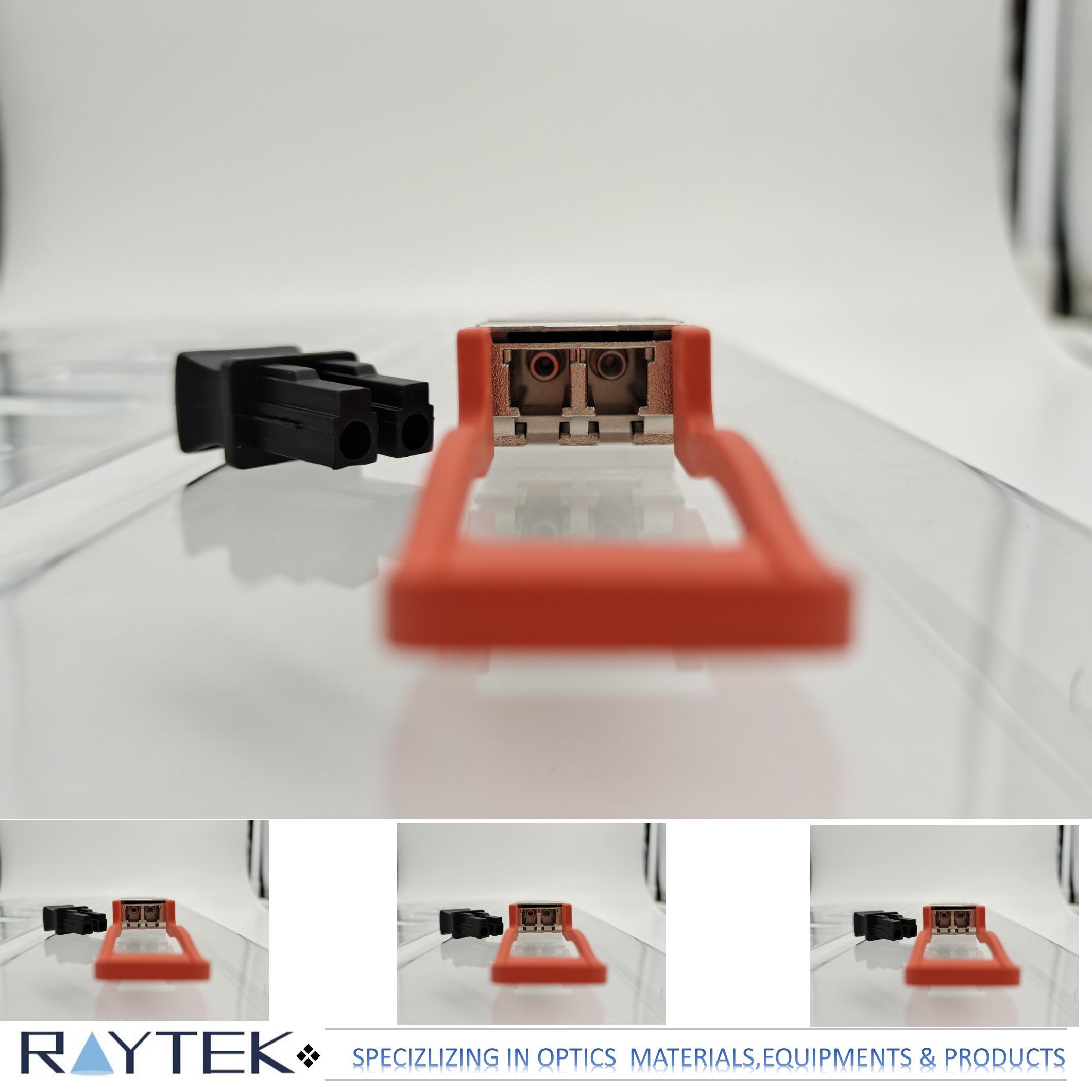
members of the CWDM wavelength grid defined in ITU-T G.694.2. It contains a duplex LC connector for the optical interface and a 38-pin connector for the electrical interface. To minimize the optical dispersion in the long-haul system, single-mode fiber (SMF) has to be applied in this module.
The product is designed with form factor, optical/electrical connection and digital
diagnostic interface according to the QSFP+ Multi-Source Agreement (MSA). It has been designed to meet the harshest external operating conditions including temperature, humidity and EMI interference.
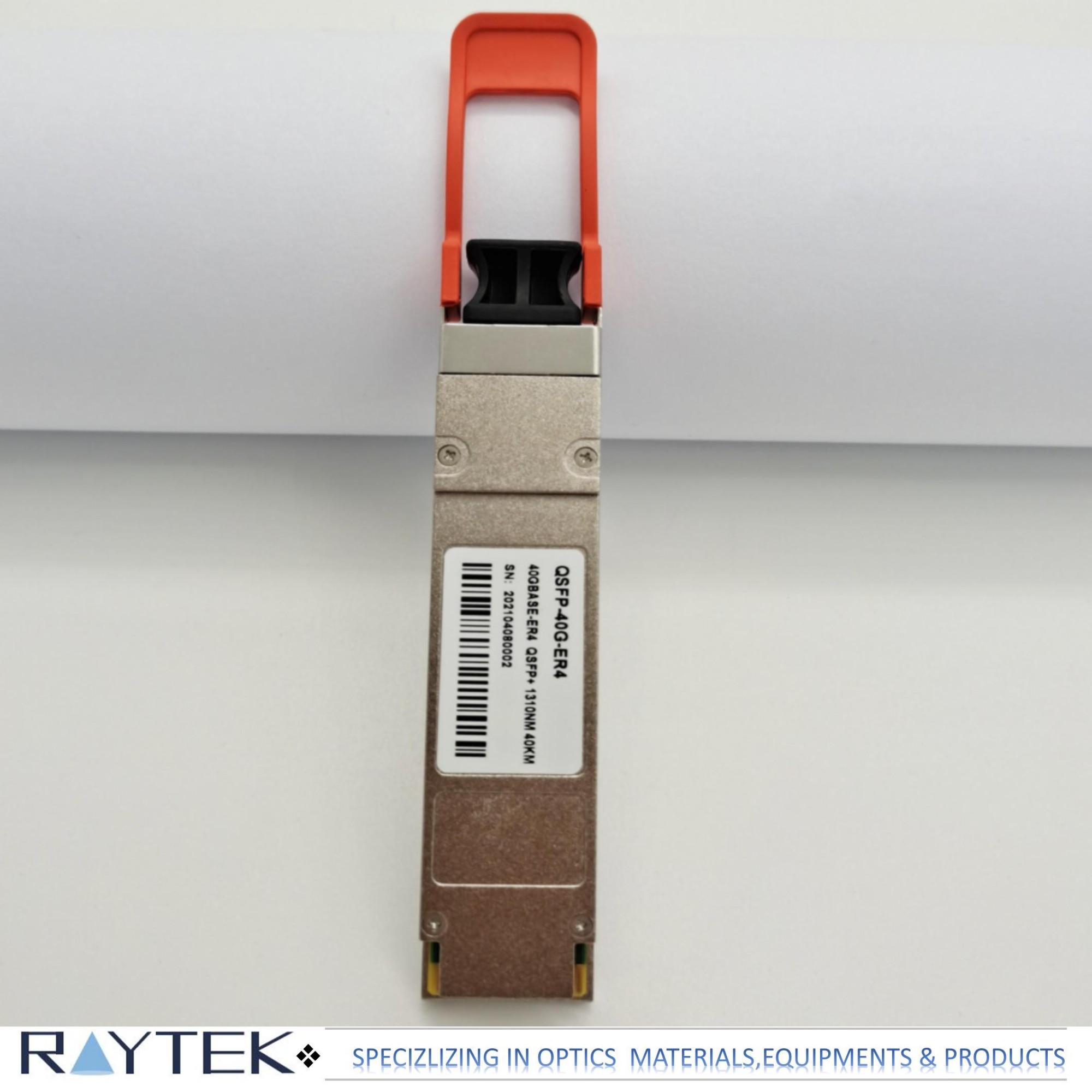
Products Name:
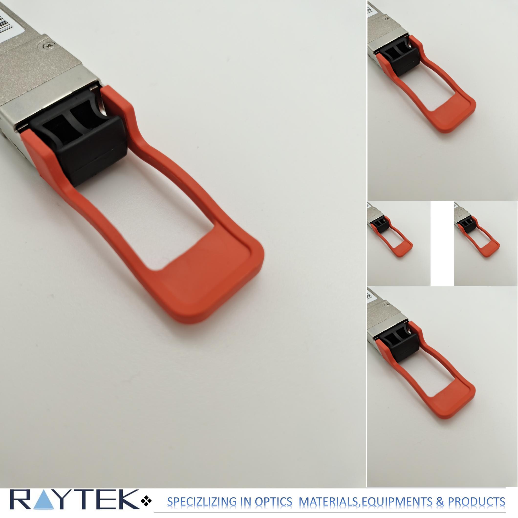
QSFP+ ER4 40km optical transceiver with full real-time digital diagnostic monitoring and pull tab
Product Features:
·1).Compliant with 40G Ethernet IEEE802.3ba and 40GBASE-ER4 Standard
·2).QSFP+ MSA compliant
·3).Compliant with QDR/DDR Infiniband data rates
·4).Up to 11.2Gb/s data rate per wavelength
·5).4 CWDM lanes MUX/DEMUX design
·6).Up to 40km transmission on single mode fiber (SMF)
·7).Operating case temperature: 0 to 70ºC
·8).Maximum power consumption 3.5W
·9).LC duplex connector
·10).RoHS compliant
Applications:
·1).40GBASE-ER4 Ethernet Links
·2).InfinibandQDRandDDR interconnects
3).Client-side 40G Telecom connections
Electrical Characteristics:
The following electrical characteristics are defined over the Recommended
OperatingEnvironment unless otherwise specified.
| Parameter | Test Point | Min | Typical | Max | Unit | Notes |
| Power Consumption |
|
|
|
3.5 | W |
|
| Supply Current | ICC |
|
|
1.06 | A |
|
| Transceiver Power-on Initialization Time |
|
|
|
2000 | ms | 1 |
| Transmitter (each Lane) | ||||||
| Single-ended Input Voltage Tolerance (Note 2) |
|
-0.3 |
|
4.0 | V | Referred to TP1 signal common |
| AC Common Mode Input Voltage Tolerance |
|
15 |
|
|
mV | RMS |
| Differential Input Voltage Swing Threshold |
|
50 |
|
|
mVpp | LOSA Threshold |
| Differential Input Voltage Swing | Vin,pp | 190 |
|
700 | mVpp |
|
| Differential Input Impedance | Zin | 90 | 100 | 110 | ohm |
|
| Differential Input Return Loss |
|
See IEEE 802.3ba 86A.4.11 | dB | 10MHz- 11.1GHz | ||
| J2 Jitter Tolerance | Jt2 | 0.17 |
|
|
UI |
|
| J9 Jitter Tolerance | Jt9 | 0.29 |
|
|
UI |
|
| Data Dependent Pulse Width Shrinkage (DDPWS ) Tolerance |
|
0.07 |
|
|
UI |
|
| Eye Mask Coordinates {X1, X2, Y1, Y2} |
|
0.11, 0.31 95, 350 |
UI mV |
Hit Ratio = 5x10⁻⁵ | ||
| Receiver (each Lane) | ||||||
| Single-ended Output Voltage |
|
-0.3 |
|
4.0 | V | Referred to signal common |
| AC Common Mode Output Voltage |
|
|
|
7.5 | mV | RMS |
| Differential Output Voltage Swing | Vout,pp | 300 |
|
850 | mVpp |
|
| Differential Output Impedance | Zout | 90 | 100 | 110 | ohm |
|
| Termination Mismatch at 1MHz |
|
|
|
5 | % |
|
| Differential Output Return Loss |
|
See IEEE 802.3ba 86A.4.2.1 | dB | 10MHz- 11.1GHz | ||
| Common Mode Output Return Loss |
|
See IEEE 802.3ba 86A.4.2.2 | dB | 10MHz- 11.1GHz | ||
| Output Transition Time |
|
28 |
|
|
Ps | 20% to 80% |
| J2 Jitter Output | Jo2 |
|
|
0.42 | UI |
|
| J9 Jitter Output | Jo9 |
|
|
0.65 | UI |
|
| Eye Mask Coordinates {X1, X2, Y1, Y2} |
|
0.29, 0.5, 150, 425 |
UI mV |
Hit Ratio = 5x10⁻⁵ | ||
| Parameter | Symbol | Min | Typical | Max | Unit | Notes | |
| Wavelength Assignment | L0 | 1264.5 | 1271 | 1277.5 | nm |
|
|
| L1 | 1284.5 | 1291 | 1297.5 | nm |
|
||
| L2 | 1304.5 | 1311 | 1317.5 | nm |
|
||
| L3 | 1324.5 | 1331 | 1337.5 | nm |
|
||
| Transmitter | |||||||
| Side Mode Suppression Ratio | SMSR | 30 |
|
|
dB |
|
|
| Total Average Launch Power | PT |
|
|
10.5 | dBm |
|
|
| Average Launch Power, each Lane | PAVG | -2.7 |
|
4.5 | dBm |
|
|
| Optical Modulation Amplitude (OMA), each Lane | POMA | -0.3 |
|
5 | dBm | 1 | |
| Difference in Launch Power between any Two Lanes (OMA) | Ptx,diff |
|
|
4.7 | dB |
|
|
| Launch Power in OMA minus Transmitter and Dispersion Penalty (TDP), each Lane |
|
-0.5 |
|
|
dBm |
|
|
| TDP, each Lane | TDP |
|
|
2.6 | dB |
|
|
| Extinction Ratio | ER | 4.5 |
|
|
dB |
|
|
| Relative Intensity Noise | RIN |
|
|
-128 | dB/Hz | 12dB reflection | |
| OpticalReturnLossTolerance | TOL |
|
|
20 | dB |
|
|
| TransmitterReflectance | RT |
|
|
-12 | dB |
|
|
| Transmitter Eye Mask Definition {X1, X2, X3, Y1, Y2, Y3} |
|
{0.25, 0.4, 0.45, 0.25, 0.28, 0.4} |
|
|
|||
| Average Launch Power OFF Transmitter, each Lane | Poff |
|
|
-30 | dBm |
|
|
| Receiver | |||||||
| Damage Threshold, each Lane | THd | 3 |
|
|
dBm | 2 | |
| Average Receive Power, each Lane |
|
-19 |
|
-4.5 | dBm |
|
|
| Receiver Reflectance | RR |
|
|
-26 | dB |
|
|
| Receive Power (OMA), each Lane |
|
|
|
-4 | dBm |
|
|
| Receiver Sensitivity (OMA), each Lane | SEN |
|
|
-19 | dBm | 3 | |
| Difference in Receive Power between any Two Lanes (OMA) | Prx,diff |
|
|
7.5 | dB |
|
|
| LOS Assert | LOSA | -35 |
|
|
dBm |
|
|
| LOS Deassert | LOSD |
|
|
-23 | dBm |
|
|
| LOS Hysteresis | LOSH | 0.5 |
|
|
dB |
|
|
| Receiver Electrical 3 dB upper Cutoff Frequency, each Lane | FC |
|
|
12.3 | GHz |
|
|
| Conditions of Stress Receiver Sensitivity Test (Note 5) | |||||||
| Vertical Eye Closure Penalty, each Lane |
|
|
2.2 |
|
dB | 4 | |
| Stressed Eye J2 Jitter, each Lane |
|
Per OTL3.4, G.8251 | UI |
|
|||
| Stressed Eye J9 Jitter, each Lane |
|
Per OTL3.4, G.8251 | UI |
|
|||


Main Export Countries & Areas:
Usa, Uk, Japan, Germany, Spain, France, Swiss, Korea, Russia, Mexico, Brazil, Argentina,Pakistan, India, Portugal, Canada, New Zealand, Australia, Saudi Arab, Turkey, Finland, Poland ,etc.
Payment Method: by T/T or Western Union.
Delivery time: 7-10 days.
Quality Warranty: Ruitaiphotoelectric(Raytekoptics) offers quality warranty for our optical transceiver products with "3R" policy. For any inferior-quality products, Ruitaiphotoelectric(Raytekoptics) is responsible for return, replacement and refund.


